Thursday, November 12, 2009

Binding Keys to Buttons

One project I worked on required a keyboard handler. Basically a handheld unit was being simulated on the computer and we wanted keyboard shortcuts for all the keys that could be pressed. The only problem with LabVIEW is that buttons on the front panel can only have function keys bound to toggle them.

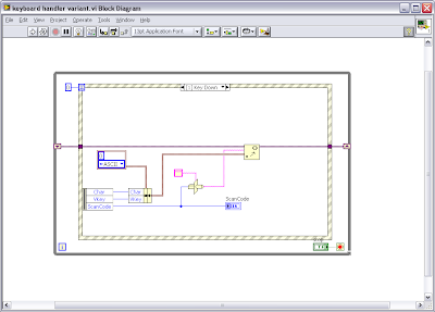
The solution involved using an event structure and capturing "Key Down" and "Key Up" events, then executing the required functionality. This blog will only be looking at how to handle the key presses. If you only want the button to respond to Key Down events your job is already done you just need to program the required functionality. The "Key Down" event will tell you the following information:

  • Char - the hex value for the ascii character
  • Vkey - ascii or special function such as enter or F7
  • ScanCode - a unique number defining each key on the keyboard

Even having mappings for * and # are fairly simple since the hex values differ to the values for 8 and 3, however they share the same physical key on the keyboard so the ScanCode is the same.

Of course the device keypad had different functionality for pressing and releasing a key. The "Key Up" event does not provide you with the same information as the "Key Down" event, unfortunately the only similar piece of information provided by the "Key Up" event is the ScanCode.

The device also has the ability to hold down multiple keys at once. In order to provide this functionality I buffered all "Key Down" event information using the set variant function. Char and Vkey were combined in a cluster as variant data named with the ScanCode typecast as a string. Then when the "Key Up" event provides a ScanCode it is typecast as a string and pumped into the get variant structure to find the Char released and perform the key release function required (This is important because * and 8 have the same ScanCode so I need to know which one to release based on the Char value generated by "Key Down"). You could use any type of buffer you like, to store the "Key Down" data, I just chose variants because retrieving variant information is order log(n) rather than n for a linear search (Darren's Weekly Nugget 10/09/2006), though probably not significant when considering we have a 10 key/finger limitation.

Monday, November 2, 2009

Custom Controls

Custom buttons in a user interface can make the interface more appealing and easier to navigate. They generally don't require much effort as long as you have reasonable image editing software.

First pick the image you wish to use for the button (This one is courtesy of the gnome user interface and comes under the GNU license be careful with licensing) and ensure it is the required size. This will be the off state image.
Make sure the background is set to be transparent, then save the image as a PNG.
Next copy the image and edit the copy, Create a new layer identical to the bottom layer directly over the top. Fill the top layer foreground with an on/off colour and then blend the images together.
This image will be the on state for the button.
In LabVIEW drop a classic square flat button and right click advanced customize.
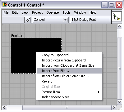
In the control front panel click on the spanner to change it to tweezers, then right click on the image import from file and choose your off state image.
Right click the control and select copy the to clipboard.
Right click the control select picture item then the third picture, right click and select import from clipboard. The image is now complete in the off state.

Repeat the process for picture item 2 and 4 with the on state image.

Click the tweezers to switch back to control mode and the custom button is finished.

Monday, October 19, 2009

ni.com/community

I've recently come across a few features on the NI website, that can all be found at ni.com/community. If you look at the right-hand side of the community webpage, there are a list of really useful links which I’ll summarise here:

1) Blogs
Here you can browse through all the blogs hosted on the NI webpage. Our LabVIEW Downunder blog has a place mark here, we’re just yet to figure out the best way of linking it to our google blog.

2) LabVIEW Ideas
This is like a suggestion box for LabVIEW. So, every time you think “wouldn’t it be great if LabVIEW could......”, just go to the LabVIEW ideas and type it in! People who like your idea will give it “kudos”, and those ideas with the most kudos end up as a high priority enhancements for the NI R&D Team. Examples that have made it into LV already are the ability to delete an object from wires and auto-reconnect the wires, and the new and improved icon editor.

3) Discussion Forums
This is where you can chat with others about specific NI questions or problems. Often, this is a great way to get support as it is monitored by lots more people, many of whom are NI employees!

4) Example Code
Got a case of “Blank VI Syndrome”? head to the example code section to see if someone has written something similar. This is a great way to get started on a project or code module quickly and save development time. You can search for specific topics or browse by product, manufacturer, application area, Industry and more.

5) Tutorials
Learn about a wide variety of topics such as issues you may face when upgrading existing code to LV 2009 (http://decibel.ni.com/content/docs/DOC-6141), How to use VI scripting (http://decibel.ni.com/content/docs/DOC-4973), and even how to interface to your Wii with LabVIEW (http://decibel.ni.com/content/docs/DOC-1353)!

6) Groups
Join groups so you can get the latest info from engineers tackling similar problems to you.

Happy Learning,

Porting DAQmx Task Configurations

Ever wondered what's the best way to port DAQmx task and channel configurations from one PC to another with minimal fuss? It is a problem we are faced as intergrators every day - how do we make the application easy for our client to install and maintain well into the future? We always need to have some sort of hardware configuration in our applications, but is it best to:

a) store that configuration information as an extra file, or should it be

b) integrated into the software application to minimise the number of files required on each target PC, making the installation process quicker and simpler for the client?

I like the idea of option b, however it seems a lot more work and therefore cost to code the hardware configuration into LabVIEW, rather than simply exporting the Measurement and Automation Explorer (MAX) configuration file to the target machine.

Something I have been using for a long time, which seems to be a little known feature of LabVIEW, is automatic code generation for DAQmx tasks. This feature makes it a breeze to convert your MAX task configurations into code. Using this, you can easily deploy hardware configurations inside your executables, and it is simple to add or modify those configurations in LabVIEW later.

Here is the trick....

1) Create and configure your DAQmx task in MAX

2) In LabVIEW, place a DAQmx task name constant on your block diagram

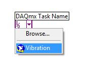
3) Pull down on the task constant and select the saved MAX task (just as if you were going to use the saved MAX configuration to run the hardware I/O functionality)


4) Right-click the task constant and select "Generate Code".

Here you have a number of options, the most usefull of which are "Configuration" and "Configuration and Example". If you have blank VI the "Configuration and Example" option is gold, as it automatically generates your while loop, stop button, graph and all those other little VIs that I always forget to include when developing DAQmx code, such as start task and stop task. It also generates a subVI, inside of which you will find all of your task configuration code. once this subVI is built, you can forget about your MAX configuration files as all the configuration information is now in your code - brilliant!

If you have already written your data acquisition code, and simply need to generate your MAX configuration code, use the "Configuration" option. This will automagtically generate a neat little subVI with a task and error output.

Go on, give it a go!


Wednesday, August 5, 2009

Updating the User Interface

Have you ever had trouble updating a chart when using a slider to control the axis?

I have tried using event cases that run on:
  • value change - updates but in a clunky manner
  • mouse up - you don't always mouse up over the slide after dragging it
  • drag end - does not update on the fly, so there is no feedback
The solution I have started using requires an event driven producer consumer. It was suggested to me by one of the LabVIEW architects at my company (CPE Systems)

The trick here is to enqueue the update case only if it is not already in the queue. If the case already exists in the queue nothing is added to the queue. When the consumer handles the case it takes the latest value from the slide itself. Providing smooth, live updates. This trick also works for other complicated user interface redraws.

Have you got any neat tricks you use to enhance the look or feel of your software?

Friday, July 24, 2009

Understanding Synchronisation with NI hardware

Synchronisation is a term commonly used when dealing with hardware timing. It is used in many different contexts with many different meanings. A recent application our company (CPE Systems) developed for a client required synchronisation between devices to determine the relatively small propagation delay between a transmitted and received signal. Getting an acceptable level of synchronisation and meeting the other requirements of resolution, sampling rates and start delays proved more challenging than first anticipated.

Our client was interested in measuring the velocity of a soundwave based on its propagation delay. The velocity of the soundwave is calculated by measuring the phase difference between the transmitter and receiver. Phase is used instead of time because it can be extracted from low level signals when lots of noise is present. We know approximately the time taken for the transmitted signal to reach the receiver, then using the phase shift we can accurately calculate this time delay. To accurately measure the phase difference between the transmitter and receiver the devices must be synchronised so the phase difference measurement does not vary between iterations.


Figure 1 - System Diagram

The receiver connects to the PXI-5922 (Digitizer) and the transmitter connects to a PXI-5412 (Arbitrary Waveform Generator). Calculating the velocity is a simple process as we have a known distance between the transmitter and receiver, and we calculate the time it takes to get there. Some high end instrumentation was required to allow us to trial a range of sampling rates, bandwidth and resolution. The hardware was chosen to meet the mega sample generation and acquisition requirement and the high resolution requirement. The PXI platform was chosen because it allows for more advanced synchronisation options.

Figure 2 - PXI Hardware

In order to achieve the synchronisation required we attempted two methods:

  1. Sharing a reference clock and external trigger source
  2. NI-TCLK

Shared Reference Clock and Trigger Source

Each of the NI PXI cards have a voltage controlled crystal oscillator (VCXO) that is phase locked (rising edges occur on rising edges of the reference clock) to the PXI 10MHz reference clock. The external trigger is connected to both devices by the same length and type of wire, to ensure both instruments receive the trigger at exactly the same time. The PXI-5412 has a generation delay of 110ns + 43 sample clock periods when no filtering is enabled and the PXI-5922 digitizer starts acquiring when the function generator is ready, so we know how far around the sensor has rotated since the start trigger. At a common sample rate of 500 kHz, the start delay is 80-82 us.

Function Generator (Rate)

Digitizer (Rate)

Phase Delay

100 kHz

100 kHz

10 us

1 MHz

1 MHz

1 us

10 MHz

10MHz

0.1 us

Table 1 - Shared reference clock and trigger source phase delay results

Phase delays measured in Table 1 represent how far a sample can shift between multiple measurements. The results show that the sample (taken by the digitizer) can be out by as much as one sample clock period when compared with where the function generator sample occurred. The phase delay determines the accuracy the velocity is calculated with.

Tclk

NI Tclk aims to have devices respond to triggers on the same sample period and have the sample clocks closely aligned. This is achieved by introducing another signal-clock domain. Each device generates this trigger clock (Tclk). It is a lower frequency than the sample clocks and calculated based on the sample clocks of all devices. The master device receiving/generating the trigger sends the trigger to all devices including itself on a Tclk falling edge. The devices then respond to the start trigger on the next rising edge of Tclk, resulting in the trigger being synchronised to a Tclk pulse. The drawback of Tclk is the lower frequency of the signal and the instance that the trigger occurs will influence the start delay. At a common sample rate of 500 kHz the start delay varies between 500-1050 us. The delay is due to the slower Tclk frequency, aligning clock edges and triggering devices.

Function Generator (Rate)

Digitizer (Rate)

Phase Delay

100 kHz

100 kHz

27 ns

1 MHz

1 MHz

4.9 ns

Table 2 - Tclk phase delay

Phase delays measured in Table 2 show that when using Tclk the time variation between samples is greatly reduced.

The Solution

In order to reduce the phase delay to an acceptable level the methods have been implemented in the following ways:

  1. Pulse Mode (Shared Reference Clock – no Tclk): This method generates and acquires data at 10 MS/s producing a phase delay of 100 ns and a start delay of 4.41 us. Due to the high sample rates this mode can only be operated in short bursts or the waveform generator and digitizer will run out of on board memory. This method allows us to get an estimate of the delay expected when using the more accurate Tclk method.
  2. Continuous Mode (Tclk): This method uses Tclk and acquires and generates data at 500KS/s producing a phase delay of around 20 ns. The start delay is varied between 500-1050 us. The velocity calculated is the average velocity for a single generation acquisition run.

For more information about Tclk visit:

http://zone.ni.com/devzone/cda/tut/p/id/3675

For more information about sharing reference clocks and triggers and other synchronisation information visit:

http://zone.ni.com/devzone/cda/tut/p/id/3615
Tuesday, March 17, 2009

Comments wanted from Embedded Systems Engineers

I have recently been spending time thinking about how tough debugging can be some times, why this is so and what to do about it.
This resulted in a whitepaper "debugging embedded systems" (http://www.clarinox.com/index.php?id=59).
I am hoping to get some comments from the embedded systems community with permission to publish these on the link (http://www.clarinox.com/index.php?id=4).

So far I have had comments from US, UK and Europe and hope to add some interesting comments from the embedded systems community in Australia.

Tuesday, March 3, 2009

Upcoming NI Workshops in March

Below are some NI Hands-On Workshops coming up in March:

1) Graphically Programming FPGA’s for Advanced Industrial Measurements and Control – Hands-on Workshop. 11 March 2009 in Glen Waverly, VIC. As part of this, CPE Systems will be giving a short presentation on a cRIO application, using LabVIEW RT and FPGA.For full workshop details, visit: http://sine.ni.com/apps/utf8/nievn.ni?action=display_offerings_by_event&event_id=1227&country=AU&site=AU&l=US

2) Introduction to PC-based Measurements and Graphical Programming with LabVIEW - Hands-on Workshop. 13 March 2009 in North Ryde, VIC. As part of this, CPE Systems will be giving a short presentation on the Portable DAQ System (PDAS) in the morning, and Balaton Technologies will be doing a short presentation in the afternoon. For full workshop details, visit: http://sine.ni.com/apps/utf8/nievn.ni?action=display_offerings_by_event&event_id=1219&country=AU&site=AU&node=160480&l=US

Wednesday, February 25, 2009

The LabVIEW Blog Explosion

LabVIEW Blogs - there's a lot of them. I found this out while setting up this very blogspot. One thing's for sure, is that the LabVIEW community is committed to using and supporting this great programming language. What was once a niche tool, is now very much the accepted platform in the test and measurement industry, among others.


I'll just take a moment to feature a few of my favourite LabVIEW/T&M Blogs that I now regularly peruse:


http://thinkinging.com/ - Written by Jim Kring, Jim is regurlarly offering wisdom and sound advice on his blog. Jim has innovation written all over him, pushing the boundaries of LabVIEW development, especially the Computer-Aided Software Engineering (CASE) side of things.


http://anengineeringmind.blogspot.com/ - Todd, from NI, provides a humourous video blog of the life and challenges of an engineer, and how engineers seem to differ from the rest of the world. Not really much about LabVIEW, but most engineers will be able to relate to his little anecdotes.


http://labviewartisan.blogspot.com/ - D Natt from NI writes a thorough blog on a variety of topics, from LabVIEW tips, to certification. A very handy resource indeed.


http://forums.lavag.org/blog/champions/index.php? - Chris Relf (from Australia!) writes some very good articles here at the LabVIEW Champions' Blog. Great reading.


http://labviewgeek.blogspot.com/ - A new blog pushing the case for Object Oriented Programming.


Want more? Then check out:


Still want more? Go here: http://zone.ni.com/devzone/cda/tut/p/id/4574

Followers